
In boatyards, ship repair facilities, and commercial marinas, 200-ton mobile boat lifts—commonly called mobile boat hoists or travel lifts – are essential for hauling out, launching, and moving vessels around the yard. Unlike shipyard cranes running on fixed rails or traditional dry docks, mobile boat lifts travel directly over paved or semi-paved ground. They handle vessels that vary widely in weight distribution, hull shape, and structural stiffness.
Designing a 200 ton mobile boat lift requires balancing frame strength, hydraulic power, steering control, ground load distribution, and marine corrosion protection. This article examines the practical engineering challenges involved in designing these large machines and outlines the practical solutions used in modern equipment design.
Structural Engineering and Frame Design
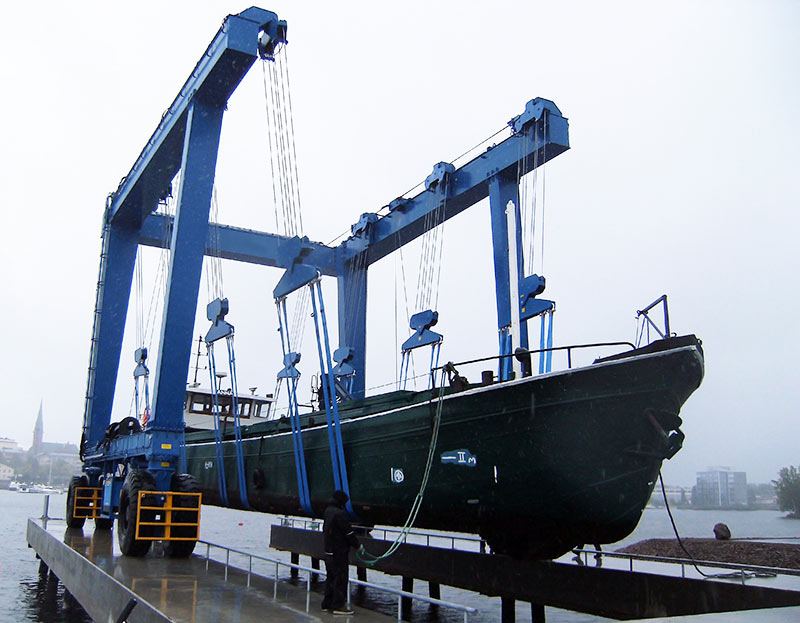
Mobile boat lifts use an open, three-sided “U-frame” steel structure. This open design allows sailboats with high masts and yachts with tall superstructures to drive directly into the interior lifting space without hitting overhead beams. Because the frame lacks upper cross-bracing along its sides, it acts as an open portal frame that experiences heavy bending and twisting forces during operation.
Managing Deflection and Frame Stress
When lifting a full load or working with an uneven weight distribution, heavy stress concentrates at the corner joints where the vertical columns meet the upper side beams. Design engineers face two main challenges:
- Controlling Deadweight: Making the steel plates too thick increases the machine’s unladen weight (often between 120 and 150 metric tons). Excess machine weight places heavy demands on the yard pavement, which can lead to costly ground reinforcement.
- Maintaining Frame Stiffness: If the structure is not stiff enough, the frame will bend excessively under heavy loads. Frame distortion causes uneven tire wear, puts extra stress on wheel drives, and leads to structural fatigue over time.
Stress Analysis and Structural Optimization
Engineers use three-dimensional finite element analysis to check frame behavior under realistic yard conditions:
- Symmetrical Lifting: A full 200 ton boat lift with equal weight across all lifting points.
- Asymmetrical Lifting: Uneven weight distribution caused by heavy engines or offset fuel tanks inside the boat.
- Torsion from Rough Ground: Traveling across uneven pavement where ground height varies by up to 50 millimeters, causing the frame to twist diagonally.
To handle localized stress without adding unnecessary weight, designers use box girders with variable cross-sections at main corner joints, reinforced internally with stiffener plates. High-strength structural steel grades, such as S355 or S690, are specified to keep structural weight manageable while maintaining appropriate safety factors.
Multi-Point Hydraulic Hoisting and Synchronization
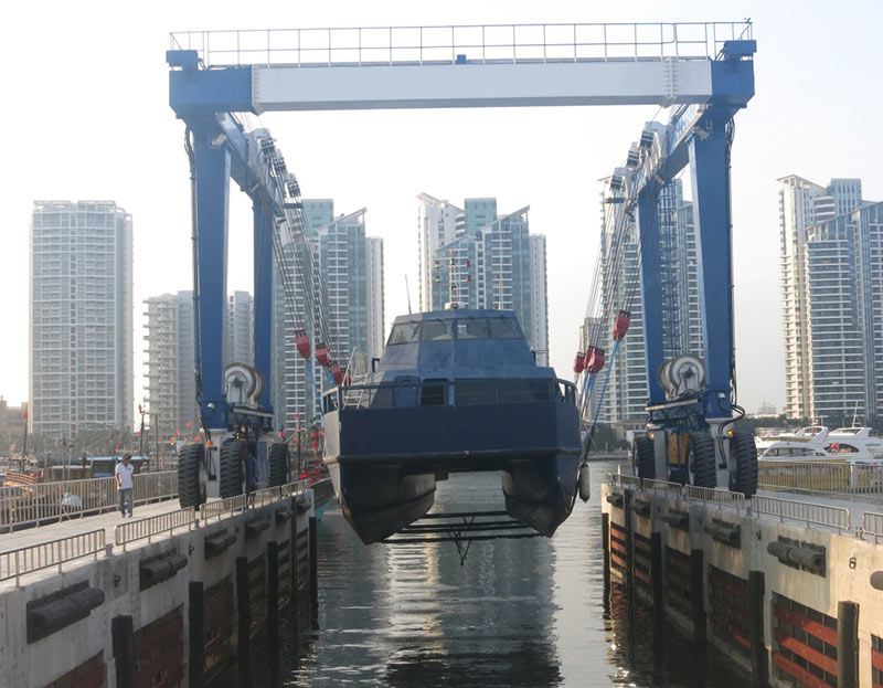
A 200-ton load is typically supported across four to eight individual hoisting points using wide synthetic slings. Because boats rarely have an even weight distribution, individual hoisting points experience different loads.
Handling Uneven Load Distribution
When lifting a boat with a heavy stern, such as a twin-diesel motor yacht, the rear winches carry significantly more weight than the front winches. In a standard hydraulic circuit, fluid follows the path of least resistance and flows toward the lighter-loaded motors. This causes lighter hoist points to move faster, tilting the vessel and creating dangerous sling slippage or hull strain.
Control System Solutions for Level Lifting
To keep the vessel level during lifting and lowering, engineers combine mechanical and electronic controls:
- Closed-Loop Electro-Hydraulic Control: Each hoist winch includes a rotary encoder and an inline load sensor. A central programmable logic controller monitors position and load readings, adjusting proportional valves to regulate oil flow to each winch motor. This system keeps elevation differences across all lifting points within a few millimeters.
- Rotary Flow Dividers: Mechanical gear-type flow dividers are installed ahead of the control valves as a physical backup. If an electronic sensor fails, the mechanical divider maintains steady oil flow to prevent sudden tilting.
- Precision Inching Control: Hydraulic winches must provide steady ultra-slow speeds (0.1 meters per minute or lower) during final positioning. This prevents impact damage when setting the hull onto storage blocks or cradle frames.
Ground Load Distribution and Steering Systems
Combining a 200-ton payload with a 130-ton machine weight produces a total operating weight of over 330 metric tons. Distributing this heavy load without cracking concrete yard surfaces requires careful wheel bogie and suspension layout.
Tire Configuration and Load Equalization
To keep ground bearing pressure within acceptable limits for typical shipyard paving, 200-ton boat lifts use 8 to 16 heavy-duty rubber tires. The gross operating weight divided by the combined tire contact patch determines the average pressure on the ground.
To keep load evenly distributed on uneven ground:
- Each pair of wheels is mounted on a hydraulic or mechanical equalizer beam assembly.
- Hydraulic suspension cylinders allow individual wheel assemblies to move up and down over drainage swales or pavement bumps, preventing single axles from overloading.
Steering Flexibility
Boat storage yards are often crowded, requiring high maneuverability in narrow aisles. The steering system must support several movement modes:
| Steering Mode | Wheel Alignment | Typical Application |
|---|---|---|
| Standard Steering | Front and rear wheels turn in coordinated arcs | Driving down main yard aisles |
| Carousel Steering | Wheels turn in opposite directions around center | Turning 360 degrees in place |
| Crab Steering | All wheels turn at the same parallel angle | Moving diagonally toward slipways |
| Transverse Steering | All wheels turn 90 degrees | Lateral movement into tight storage bays |
Each wheel bogie uses an independent hydraulic slewing drive or steering cylinder managed by a digital controller that coordinates wheel angles based on the selected steering mode.
Hull Protection and Adjustable Sling Layouts
Unlike standard industrial cranes that hook into rigid lifting eyes, boat hoists carry fragile hull structures. Composite fiberglass, carbon fiber, and thin aluminum hulls can bend or crack if loaded improperly.
Longitudinal Sling Adjustment
A boat’s internal bulkheads and underwater fittings (such as propeller shafts, rudders, and bow thrusters) dictate where slings can safely press against the hull. To align slings with internal structural bulkheads, the upper hoist trolleys move forward and backward along the main top beams. These trolleys are driven by hydraulic cylinders or rack-and-pinion systems capable of adjusting positions while holding weight.
Pressure Reduction Techniques
- Wide Woven Slings: Slings are made from high-strength polyester webbing (150 to 300 millimeters wide) fitted with sliding protective sleeves to prevent abrasion.
- Swiveling Equalizer Blocks: Sling attachment points swivel to match the deadrise angle of the hull, preventing the outer edges of the straps from cutting into the hull structure.
- Spacers and Extension Straps: For deep-draft vessels or catamarans, extended slings and center-line pad spacers keep strap angles wide enough to avoid squeezing upper hull sides.
Corrosion Protection in Marine Environments
Mobile boat lifts operate in harsh coastal environments with high salt exposure, humidity, and direct seawater contact during haul-outs. Without proper corrosion mitigation, structural steel and mechanical components deteriorate rapidly.
Coating Systems for Structural Steel
Protecting the steel structure requires thorough surface preparation and specialized coating systems:
- Surface Preparation: Steel surfaces are abrasive-blasted to an ISO 8501-1 Sa 2.5 finish, producing a surface profile depth of 50 to 75 microns.
- Multi-Layer Paint Application:
- Primer Coat: Zinc-rich epoxy primer applied at 70 microns dry film thickness for sacrificial corrosion protection.
- Intermediate Coat: High-build epoxy coat applied at 150 microns dry film thickness to create a moisture barrier.
- Finish Coat: Polyurethane or fluorocarbon topcoat applied at 80 microns dry film thickness for UV protection and color stability. The total paint thickness reaches at least 300 microns.
- Internal Box Protection: Fully sealed box girders prevent internal rusting. Unsealed hollow spaces receive rust-inhibiting wax coatings and low-point drainage holes.
Component Surface Treatment
- Cylinder Rod Coating: Exposed hydraulic cylinder rods use double-layer nickel-chrome plating or high-velocity oxygen-fuel ceramic coatings to prevent pitting in salty air.
- Electrical Enclosures: Control boxes and sensor housings carry IP66 or IP67 ratings. External hydraulic fittings, clamps, and hardware use 316L stainless steel or zinc-nickel coatings.
Safety Redundancy and Fail-Safe Systems
Lifting expensive vessels weighing up to 200 tons requires reliable safety backups to prevent accidents from mechanical or hydraulic failures.
Braking and Hydraulic Protection
- Dual Winch Brakes: Hoist winches feature two separate brakes: a spring-applied, hydraulically released multi-disc brake on the drive shaft for routine stopping, and a direct drum brake on the winch flange for emergency holding. The drum brake holds the load even if a gearbox shaft fails.
- Hose-Burst Valves: Counterbalance valves are mounted directly on hydraulic cylinders and motor ports. If a hydraulic line ruptures, these valves lock immediately to hold the fluid in place and trap the load.
Electronic Monitoring Interlocks
- Load Monitoring: Real-time load cells at each hoisting point measure vessel weight and calculate center of gravity. If the total load exceeds 105% of rated capacity, an alarm sounds. At 110% overload, all upward hoisting functions are automatically locked out.
- Inclinometers: Dual-axis tilt sensors track machine level. If ground settlement causes the frame to tilt beyond 2 to 3 degrees, high-speed travel functions shut down automatically.
- Wind Sensors: Anemometers measure wind speeds, alerting the operator when wind speeds exceed safe working limits (typically 15 to 20 meters per second).
Conclusion
Designing an Aicrane 200-ton mobile boat lift involves practical engineering trade-offs between frame flexibility, lifting precision, maneuvering capabilities, and material durability. Rather than relying solely on extra steel weight, modern designs rely on detailed stress analysis, proportional hydraulic controls, flexible suspension systems, and marine-grade protective coatings. These integrated systems allow boatyards to move heavy, high-value vessels safely and efficiently year after year.